Unlocking Full Shell Functionality UART RX Mitigation Bypass on TL-WR841N
Published on Sep 27, 2024 by IoTSecurity101 Team
1. Introduction
Purpose and Motivation:
Explain why you decided to perform security research on the TL-WR841N router. || We almost bought 20+ routers from a dealer for security research and for training purposes a couple of months back. While we had bsides bangalore coming up we decided to do provide hands on training with commercial devices and so we picked up our TL-WR841N. We wanted to ensure that everything is working fine so we decided to test out UART and other things 6 hours before the training and when we tried UART we coulnd’t send any commands on RX of the device but we could see the serial logs. The IoTSecurity101 loves working for nights and how could we let go of this? So we started with our PCB RE and the journey Continued.
Please note that this is not another UART shell access blog. Instead, we will focus on how to bypass OEM mitigations that prevent access to RX. As we always say, UART all by itself is not a vulnerability but a misconfiguration. However, what you can do with UART is what matters and becomes one part of your exploit chain.
Research Goals:
Outline the main objectives, such as bypassing RX on the UART port to gain full shell access. One of the main Goals of this blog would be to show you guys how you can remove the mitigations placed on your UART port which prevents you from getting full shell access. Full shell access means having both Rx and Tx working.
2. Initial Research and Discovery
Initial Setup:
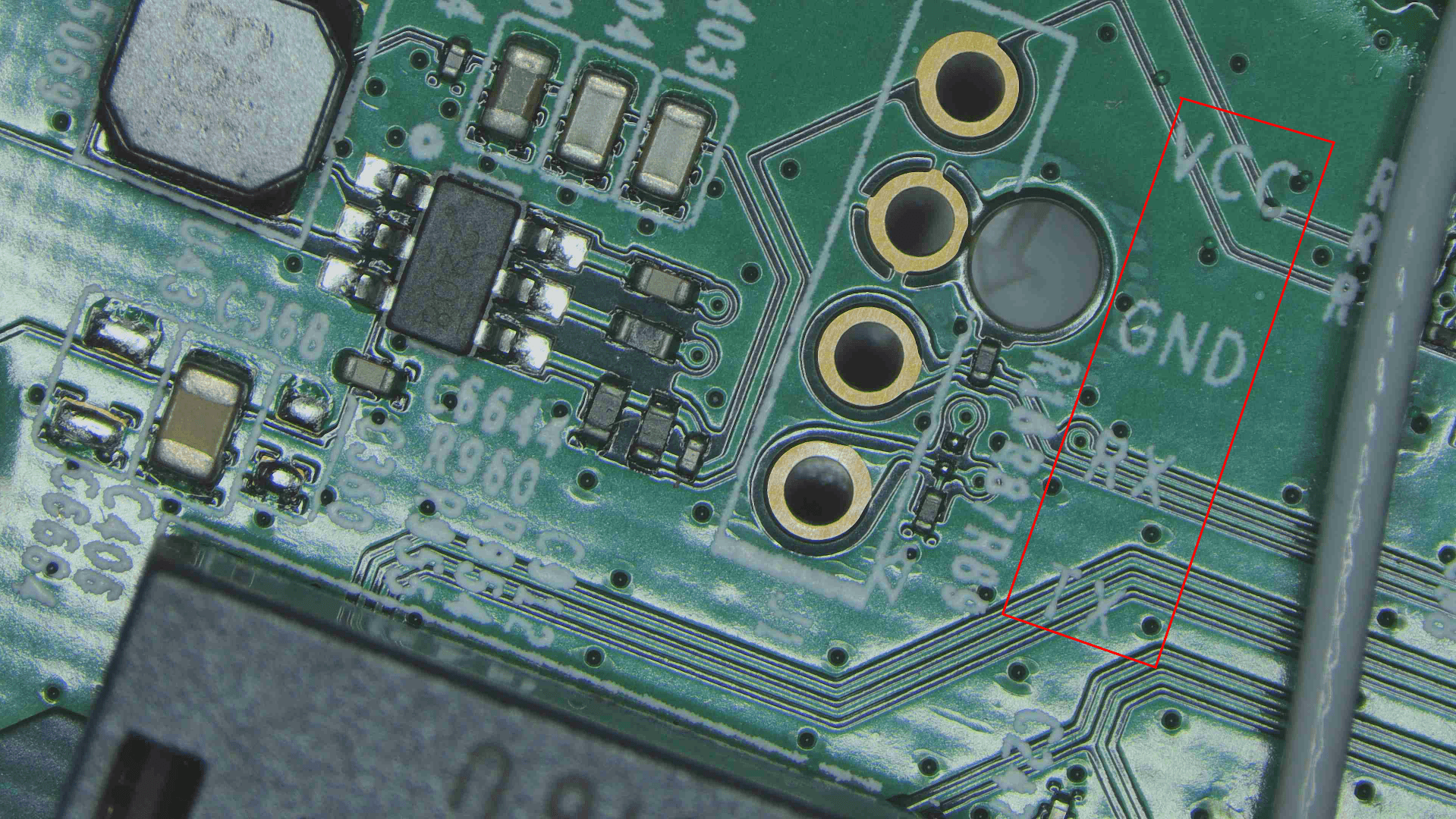
Describe how you started the research, including any initial challenges. The US make had UART pins labelled. as shown in the image below
 The EU make has got no UART Pins labelled. As shown in the image below
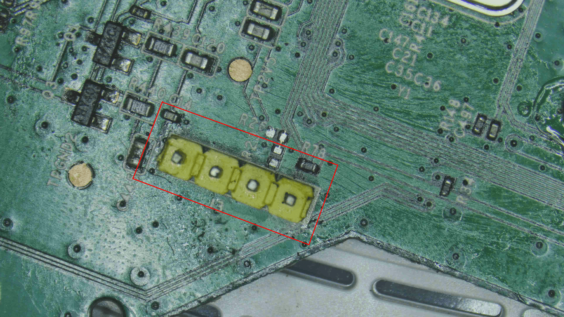
In case there is no silkscreen like the one we had in EU region we can use the below mentioned techniques to find out pins and also never trust the silkscreen marking that’s coming from OEM , its always better that you verify with a multimeter. So the steps you can take is
- Verify the ground using the multimeter’s continuity test. To do this, connect one probe of the multimeter to the suspected ground pin (such as the ground pin on the UART header) and the other probe to the 4th pin of the SPI NOR Flash chip, which is usually the ground pin on these chips. If the multimeter beeps and shows a low resistance value, typically between 0.1 to 0.3 ohms, it confirms a proper ground connection. Ensure the device is powered off during this process to avoid any damage or inaccurate readings..
- Now with the previously identified ground measure the Tx voltage and if you see the voltage fluctuating we can confirm it is Tx.
- Keeping the ground measure the Vcc and if it remains constant without any fluctuation we can take it as Vcc.
- The Rx is generally zero but if you have Rx pin showing you a value equivalent to the Vcc voltage then it could mean that there is a presence of pull up resistor.
There are other other ways to identify UART like making use of an logic analyzer and with which you can also calculate the baud rate.
Before doing all of this google and see if someone has already done it for you, if someone has give them all the credits for making the job easier for you.
Discovery of Regional Differences:
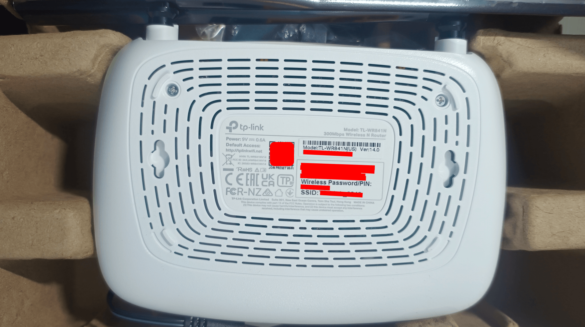
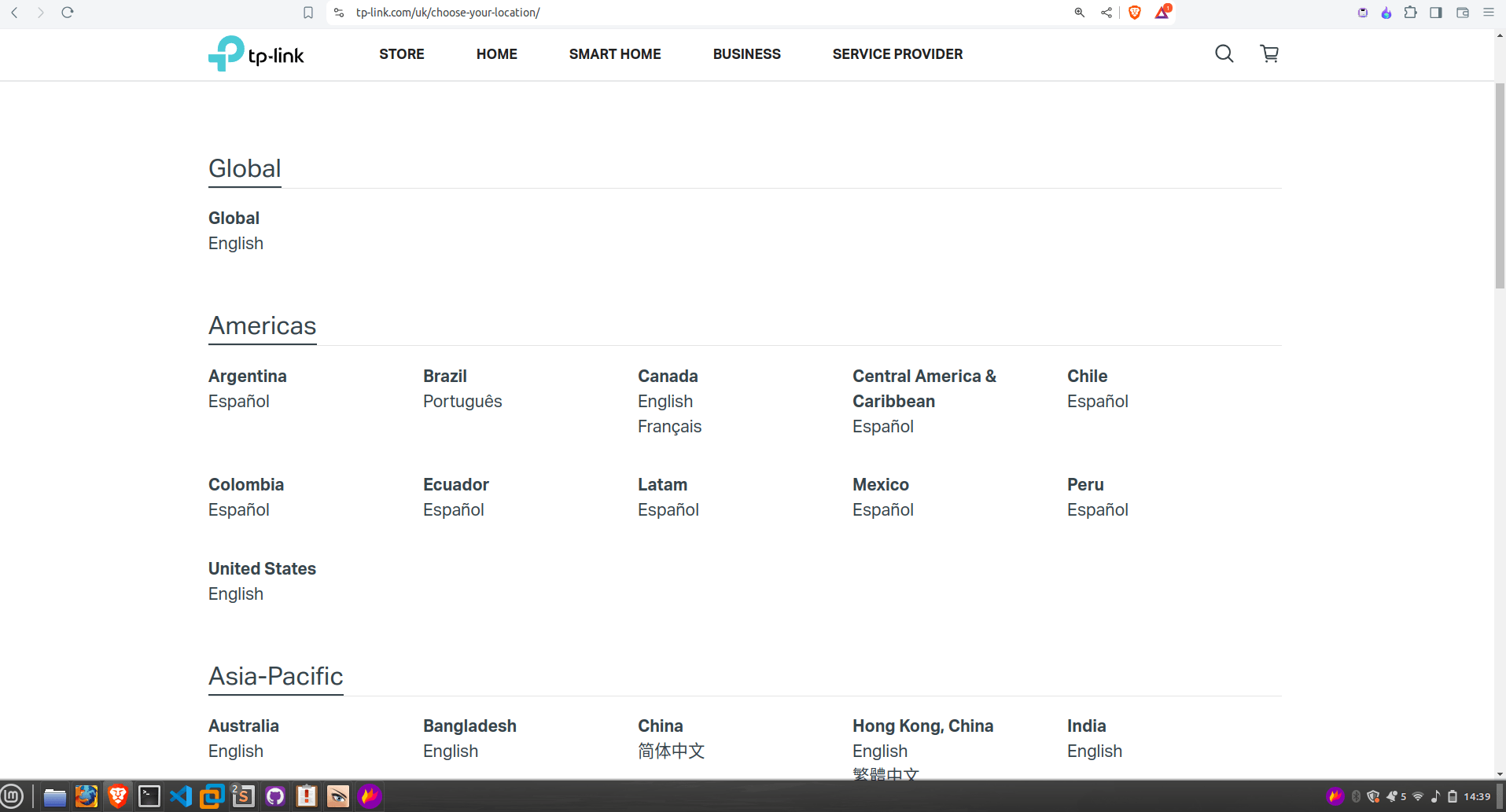
Explain how you found that the EU region router had different mitigations compared to the US region router. So when we tried to get UART a day before the bsides training, we had the EU model which we had procured it through a dealer. When we decided to write a blog for it , we decided to go for a new device which we ordered through amazon and you can see the amount of people who have rated this model its almost 1,00,000+ and now think how many might have purchased the same model. 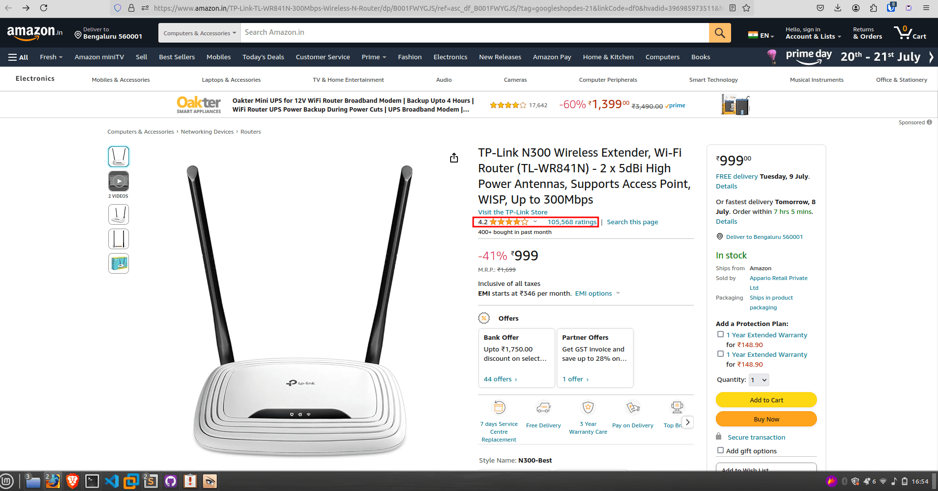
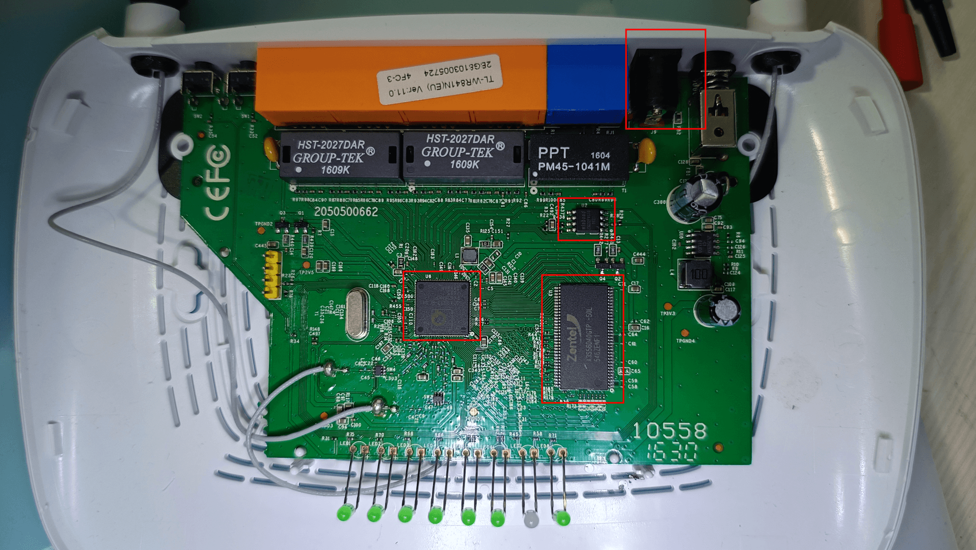
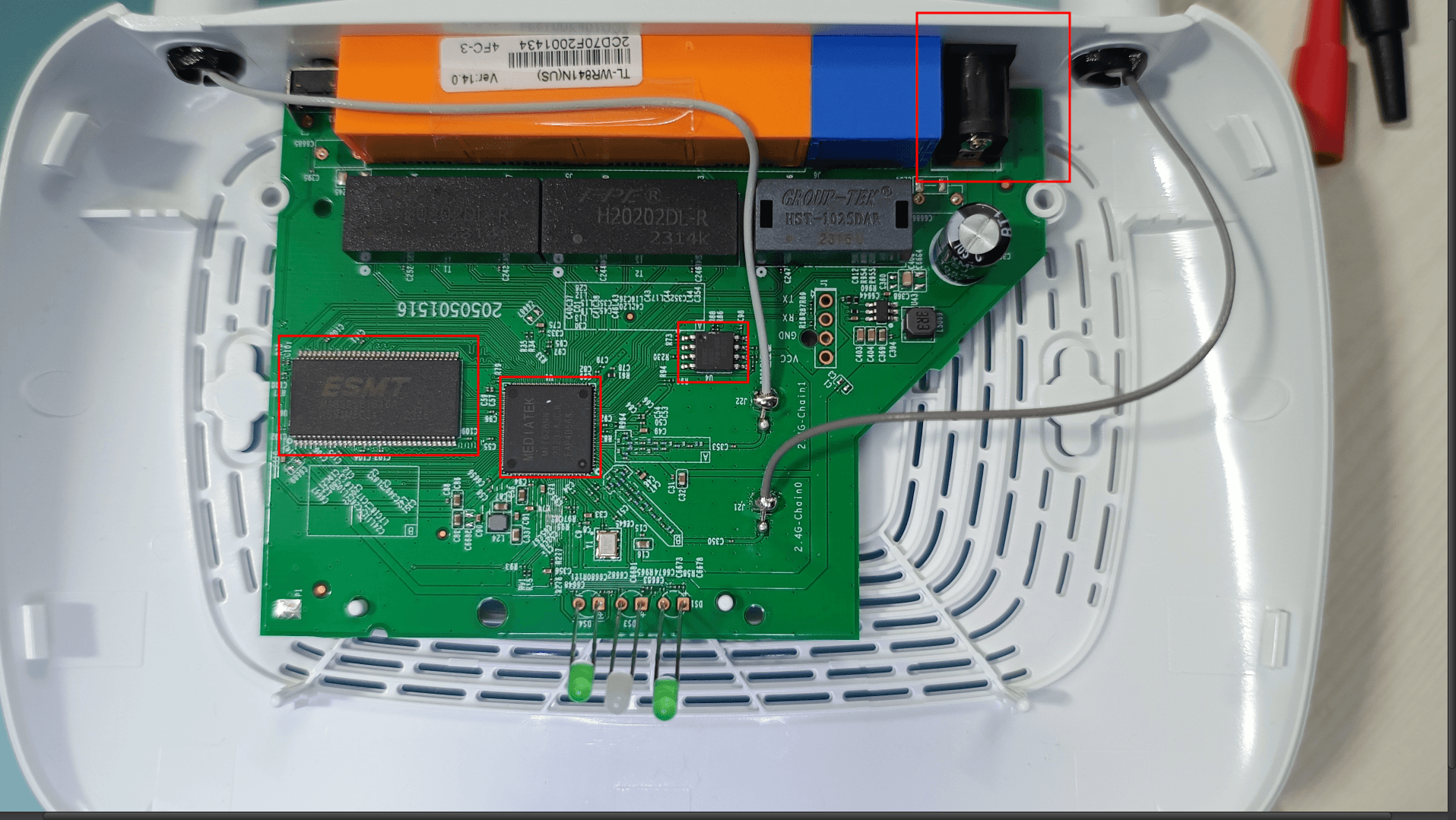
After opening the device we realise the UART pins are not soldered and the build is completely different and you can identify the difference below 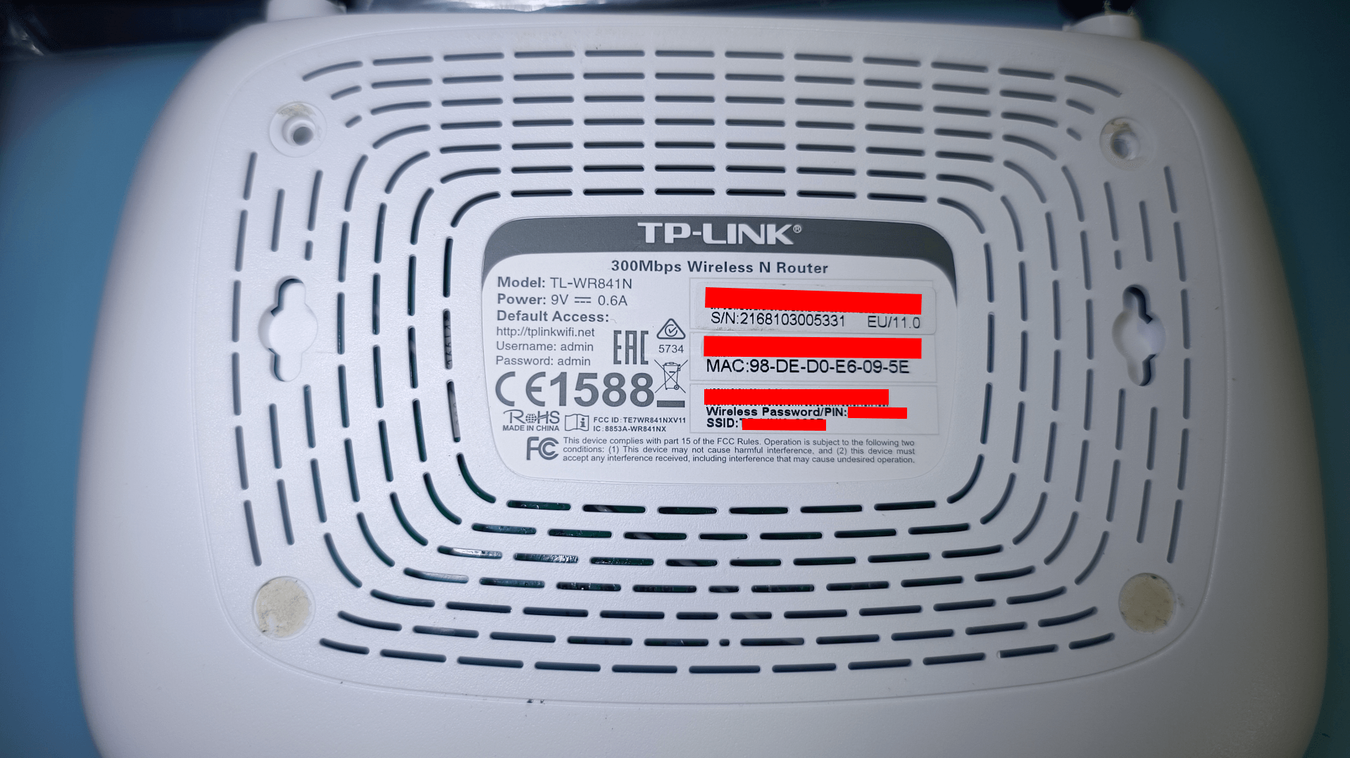
- FCC ID of EU Make - https://fcc.report/FCC-ID/TE7WR841NXV11
- FCC ID of US Make(The one we ordered through amazon India) - https://fcc.report/FCC-ID/2AXJ4WR841NV14
Differences to be noticed
- The cpu, volatile and non volatile memory are from different manufacturers all together.
- FCC ID’s are different.
- The EU region router has an extra power switch.
We can see this from the website as well
3. Understanding Regional Security Differences
EU Version vs. US Version: Discuss the security differences between the EU and US versions of the router, emphasizing why these differences are significant.
| No | US Make | EU Make |
|---|---|---|
| 1 | CPU: Mediatek MT7628NN | CPU: Qualcom QCA9533-BL3A |
| 2 | Volatile Memory: ESMT | Volatile Memory: Zentel |
| 3 | Non-Volatile Memory: cFeon | Non-Volatile Memory: winbond |
| 4 | FCC ID - 2AXJ4WR841NV14 | FCC ID - TE7WR841NXV11 |
| 5 | No extra power switch | Has an extra power switch |
| 6 | No Header pins on UART | Has got yellow color header pins on UART already soldered |
| 7 | it has got the silkscreen marking | It has got no silkscreen marking |
If the header pins are yellow then it generally means these have come soldered from OEM side only. (common observation doesn’t have to work in every case)
Impact of Regional Mitigations:
Explain how these mitigations affect the security research process and outcomes.
- Different countries get a different make.
- This could also mean the mitigations could also vary and so will the security of it.
- It would be interesting to explore devices of different regions as it could lead different findings
- EU region make could be more stringent than others, so the vulnerabilities patched in EU make model could be still be exploited in devices of other regions.
4. Technical Breakdown: Bypassing RX on EU Version
Step-by-Step Guide:
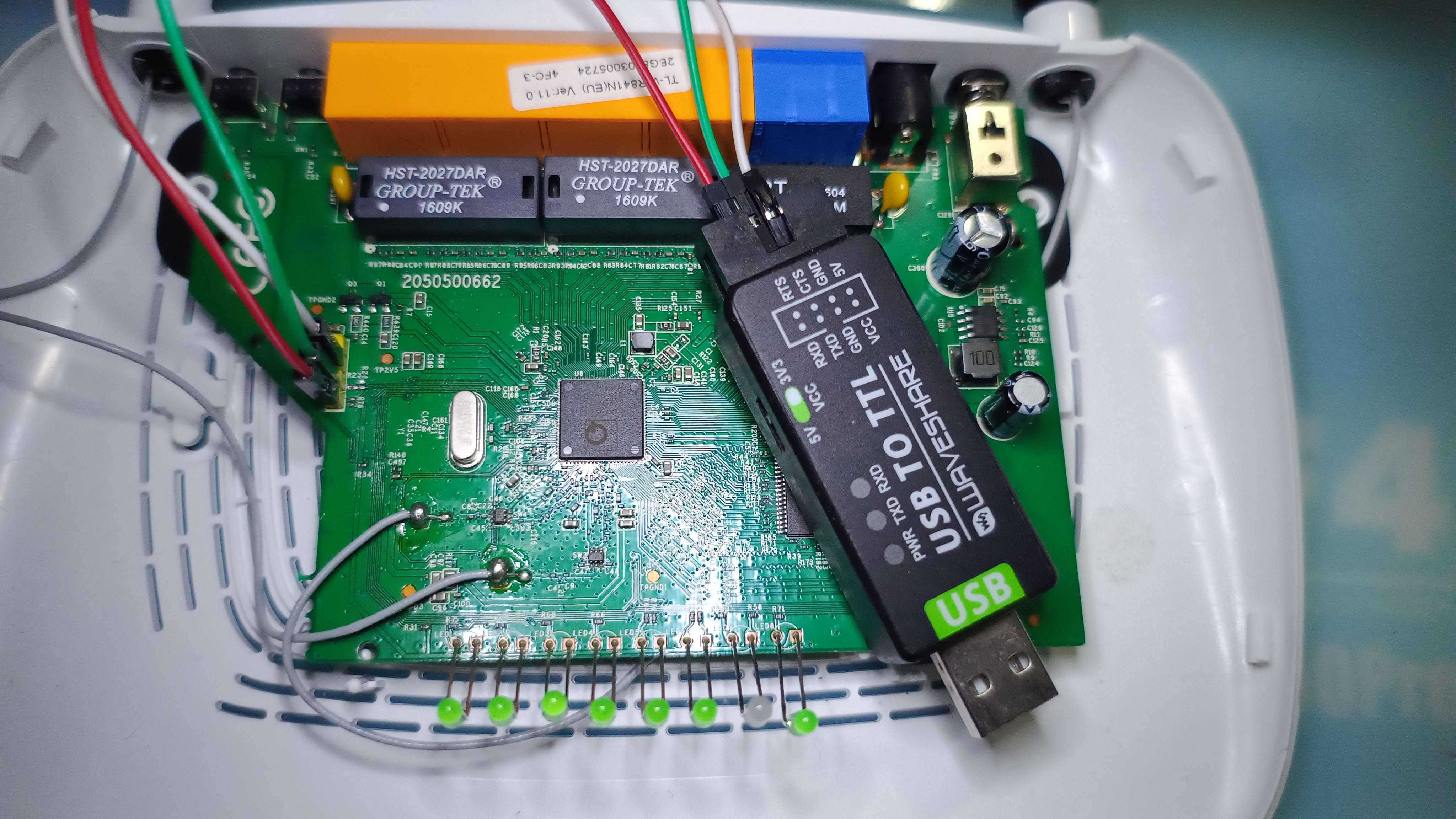
Provide a detailed, step-by-step explanation of how you bypassed RX on the EU version of the router.
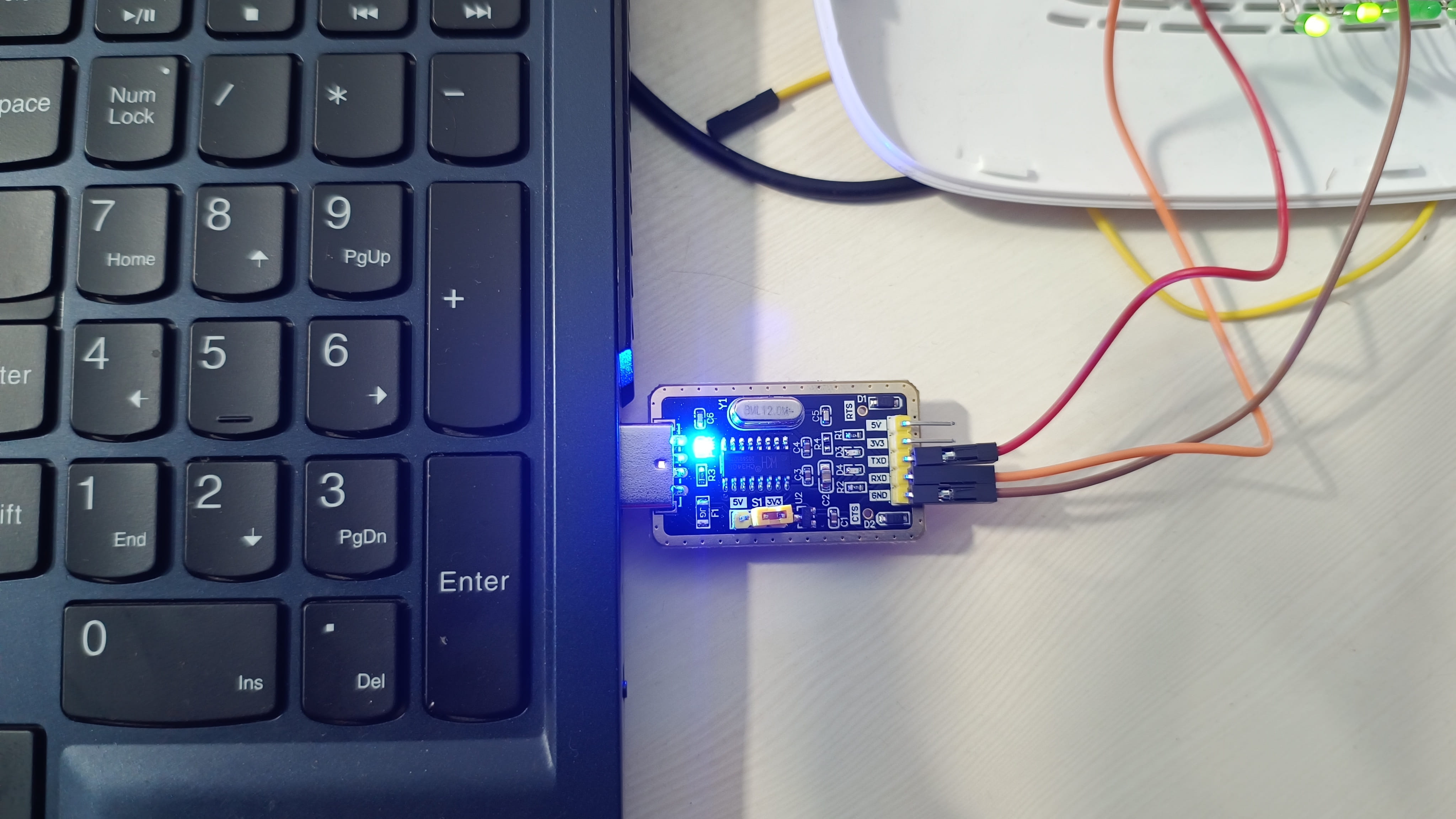
- We made use of a waveshare USB to TTL converter
- We identified the voltage to be of 3.3v through multimeter
- We confirmed the ground through multimeter continuity test
- We hook up the Tx of the device to Rx of the debugger and vice versa for Rx and gnd has to be connected.
- We finally get to see the serial logs and hurray??
OEM is like “Hurray? not so soon”, when we try sending the command through our debugger we cannot see it being reflected over the screen terminal. To Ensure that my debugger is sending the data, have a look over the Tx whenever I am trying to send data to the device through the debugger I can see the light blinking just like below attached video
sudo screen /dev/ttyUSB0 115200 # 115200 is the identified baudrate
- Challenges and Solutions: Highlight any challenges you faced during the process and how you overcame them.
- The main challenge would be the perform PCB RE and find out if we can identify what mitigation is in place
- we have to be very careful as we might accidently break or damage something on the PCB RE.
PCB RE on EU Make model
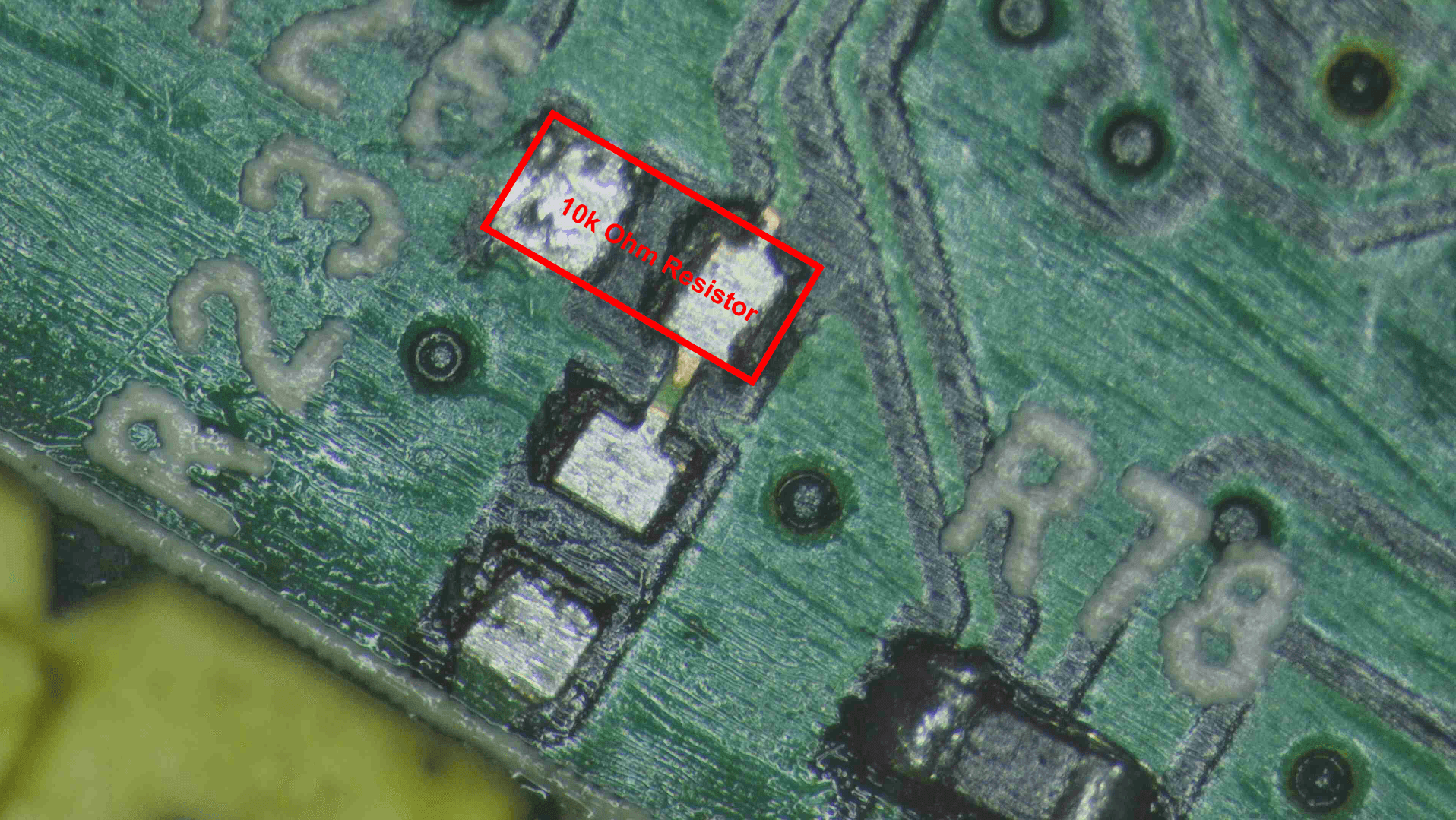
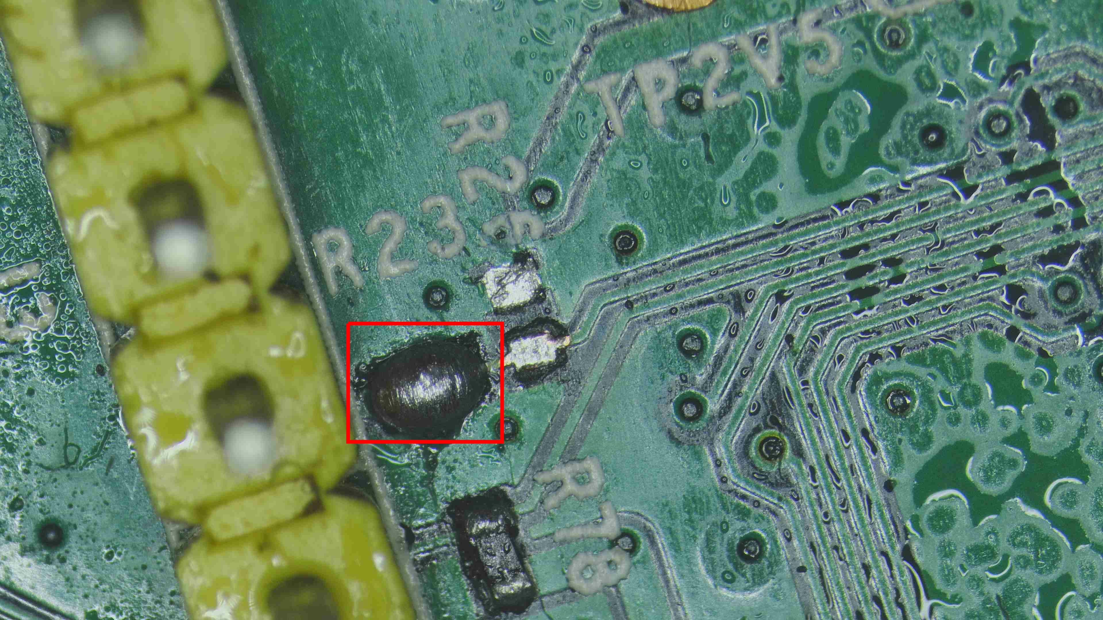
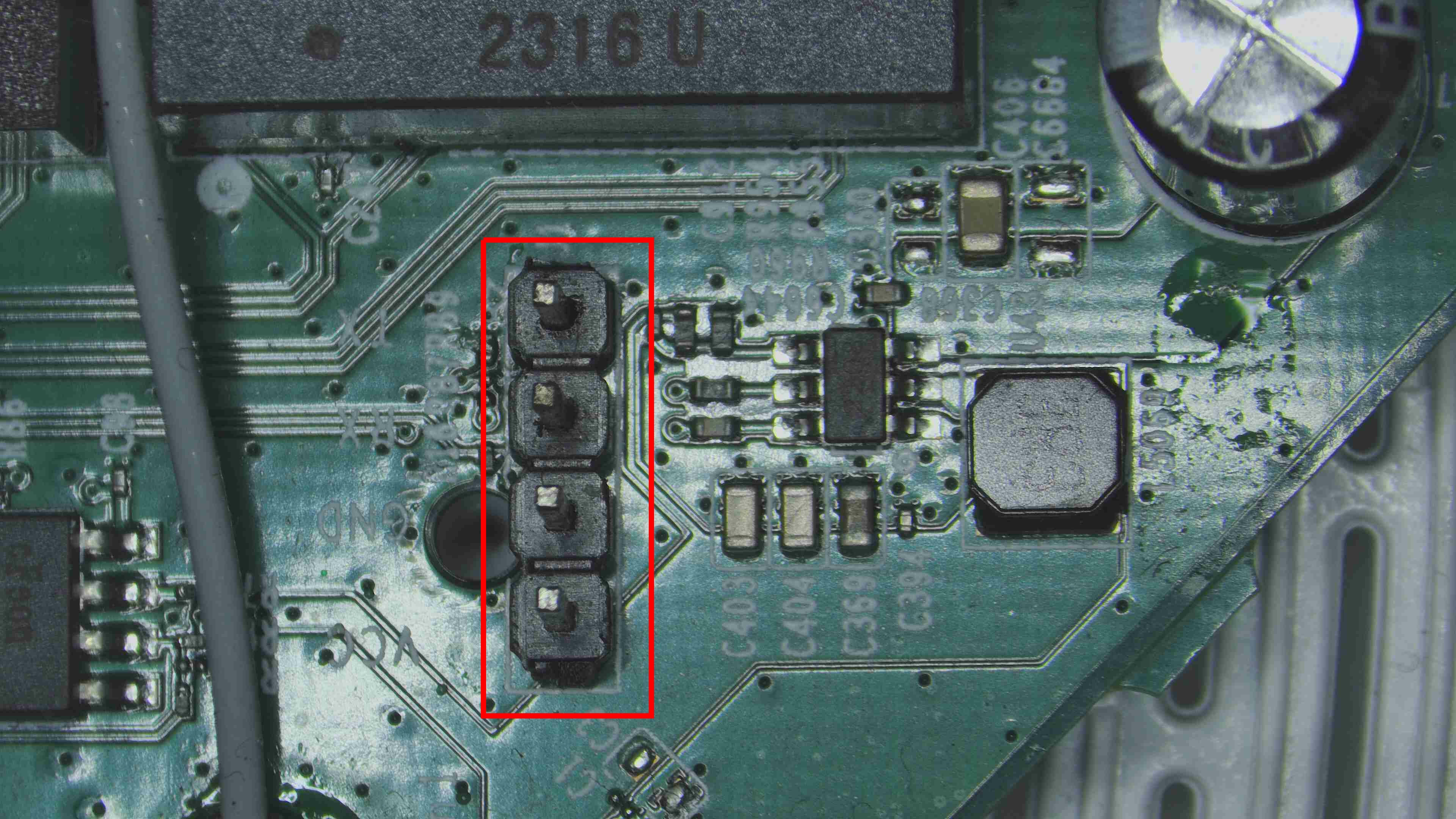
- We can see a resistor in the way of RX as shown in the image below. so let us bring out our multimeter again.
While measuring using multimeter remember how a multimeter measures the resistance. it supplies a small known current to flow through the resistor and measuring the resulting voltage drop across it. It then applies Ohms law (v=IR) which states that resistance is equal to voltage divided by current, to determine the resistance. By using a very small current the multimeter ensures the resistor doesnt heat up which helps maintain an accurate measurement. So when you have resistors in parallel and when you try to measure the resistance value using the multimeter the value will be wrong as current will always choose to flow in the least resistant path. So in case you have such parallel resistor then you will have to desolder the resistor from the pcb and then measure it. You will be lucky if you have numbering on top of the chip resistor as you can directly calculate the resistance value out of it but in most cases you will not find the numbering on top as it adds cost to the manufacturer
In our case there was only a single resistor and we could directly measure for the resistance value of the pcb board. We got the value to be of 9.9k ohm so we can round it of to 10k ohm. The other side of the chip resistor is connected to the ground and this can be verified with continuity test. So if you remember we initialy found out the voltage to be 0v on Rx so with this resistor of value 10k ohm and the other end connected to the ground we can name this is pull down resistor. We have provide the difference between pull up and pull down resistor below
The general pull up / pull down resistor value varies from 1k - 10k ohm
Now let us go ahead with removing of the chip resistor using a SMD Rework station and a nozzle of small size. You will have to be very careful doing this because during this process you will also heat the other components around and you might blow it up. Watch out (Comprehensive eMCP Desoldering Guide - Part 1)[https://www.iotsecurity101.org/blog/comprehensive-emcp-desoldering-guide---part-1] to learn more about SMD Rework station air pressure and temperature.
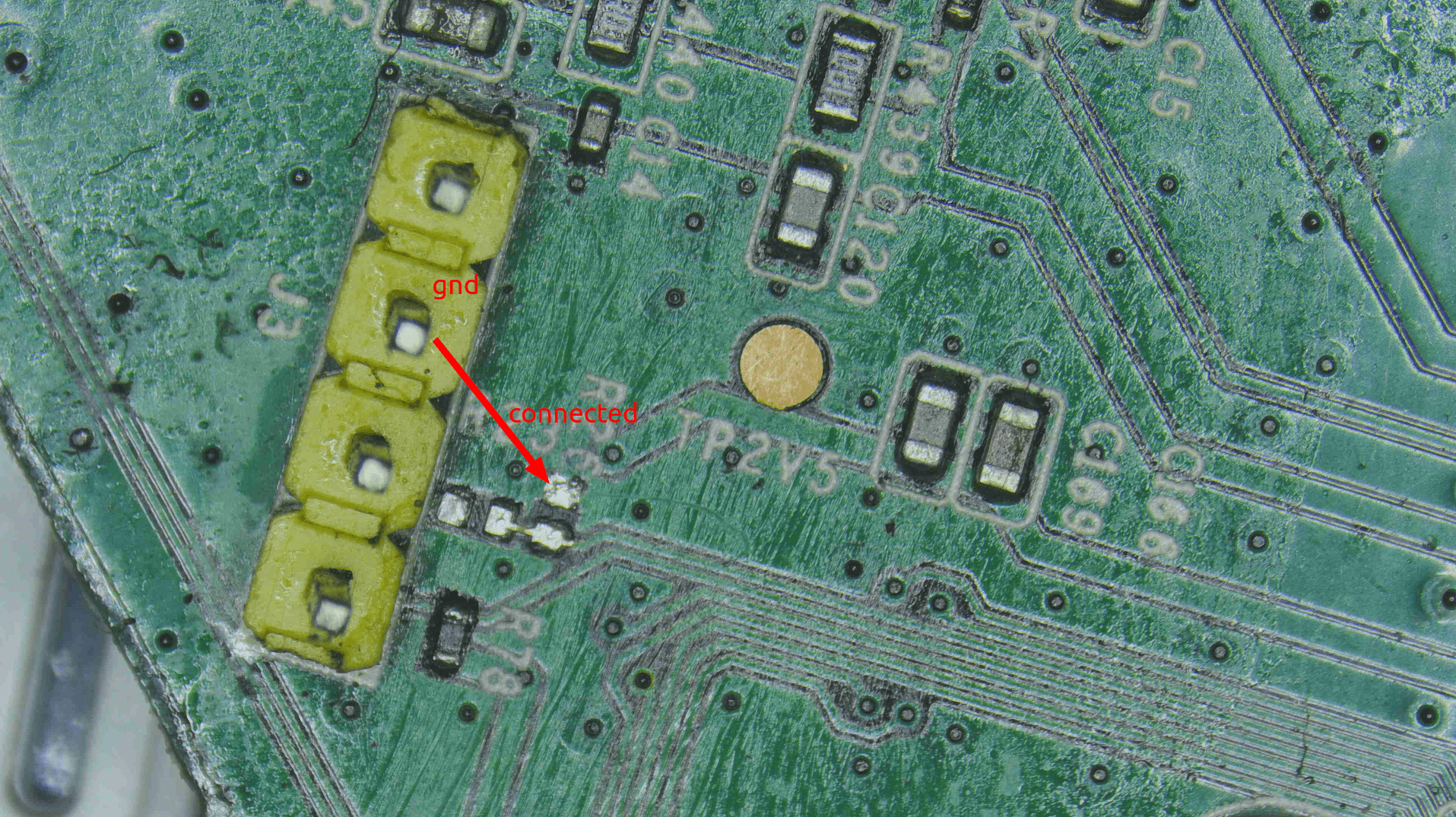
Now we have removed the 10k ohm resistor. With this action we should most probably be able to send commands over the Rx on the device. Right? That’s what we thought at the start but to our surprise we still couldn’t send commands over the Rx. Always remember KISS principle - Keep it simple and stupid. Kudos to design principle first noted by the U.S. Navy in 1960. Coming to our help again the continuity test(multimeter). As shown in the image below, the chip ressitor pad is not connected to the pad that is connected to the Rx.
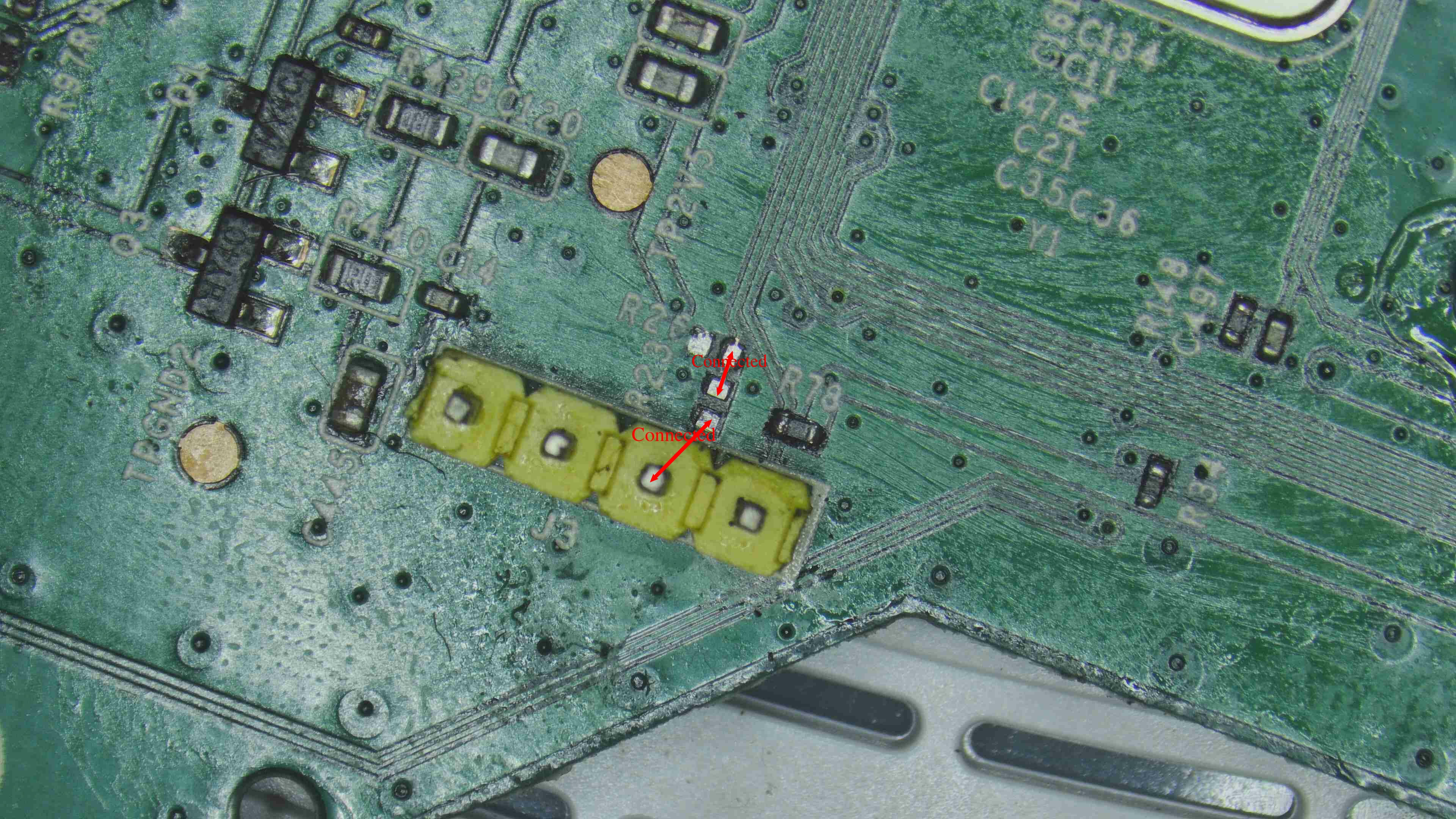
So Now we will get continutity between them by either soldering or making use of a jumper wire.
In our case we have made use of solder lid to get the continuity test but the drawback in this method is that it has got higher chances of destroying the pads(which we did and we will also show you how we overcame this situation). So we would highly recommended that you make use of jumper wire.
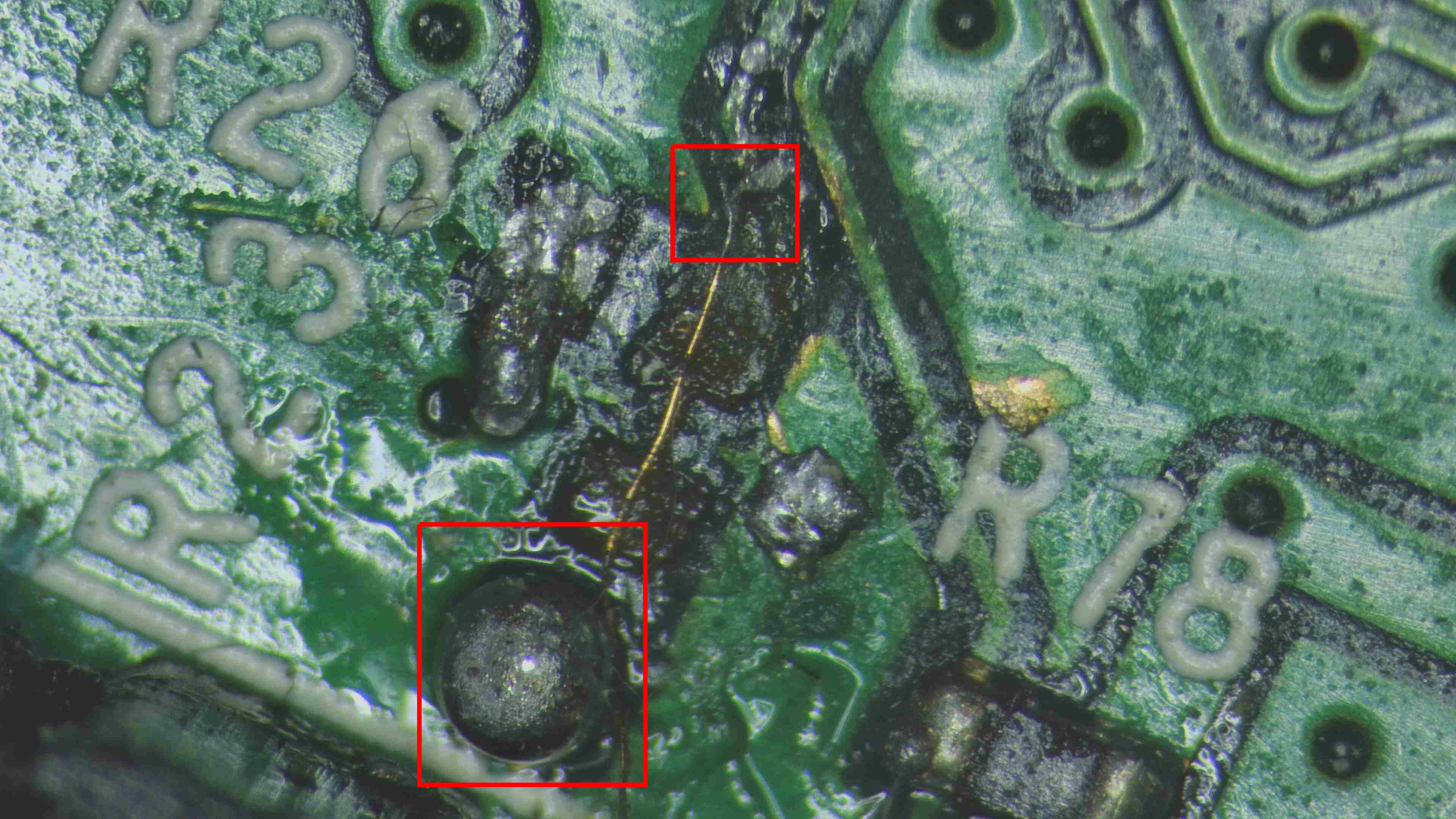
In our case due to excessive soldering attempts with a solder lid we broke the pads and so we made use of a pcb driller to etch the coating of the track and get to the conductive layer and made use of a jumper wire performing microsoldering to get the Rx enabled. Voila, we have a working shell!!
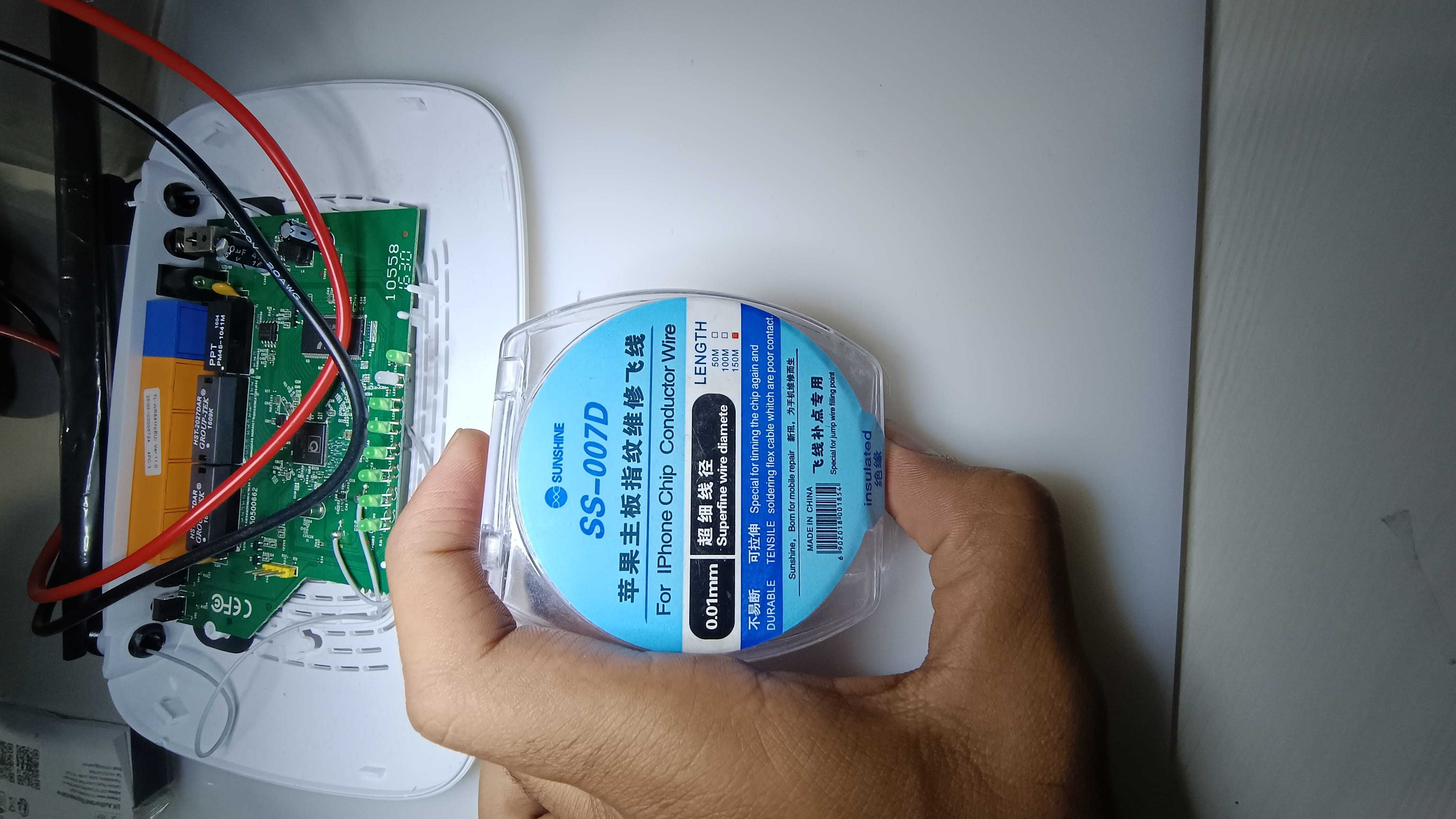
- We have made use of inexpensive CH340G USB to RS232 TTL(https://www.flyrobo.in/ch340g-usb-rs232-ttl-auto-converter-adapter-module-for-arduino?tracking=ads&tracking=4a9a9a&gad_source=1&gclid=CjwKCAjw7s20BhBFEiwABVIMrRat_pruQzpB1QAHHFxxbIPm5UnkJSkJkkn4VRKU260fJ3T4Fd5A3BoC__sQAvD_BwE) that costs about 2$.
Fun Reminder: Always check out your jumper wires that you are connecting to your debugger as to whether they are working or not because I literally had to microsolder and desolder for almost 5 times and then I realized that the issue is with my wife. The reason why the jumper wire went bad is because of the removing the chip resistor through SMD rework station and while doing so I had kept my jumper wires attached. So always remember to remove all the wires before performing any soldering or heating along with it remember the KISS principle we highlighted above! Haha!
While We are writing this blog, we had already performed bypass for almost all the devices a night before for the attendees of the training as they couldn’t do it. so we will not be able to show you actual one with the resistor and that is the reason why we have added the reading below.
5. Technical Breakdown: US Version Sold In India
Step-by-Step Guide:
Similarly, provide a detailed guide on how you bypassed RX on the US version of the router.
Comparative Analysis:
Compare the process with the EU version, noting any differences in techniques or challenges.
In here I would not be repeating the process from the start as we have already convered that in our previous section for EU region router.
Couple of things to notice in this US version router is that
- Silkscreen marking is already present
- No Header pins soldered
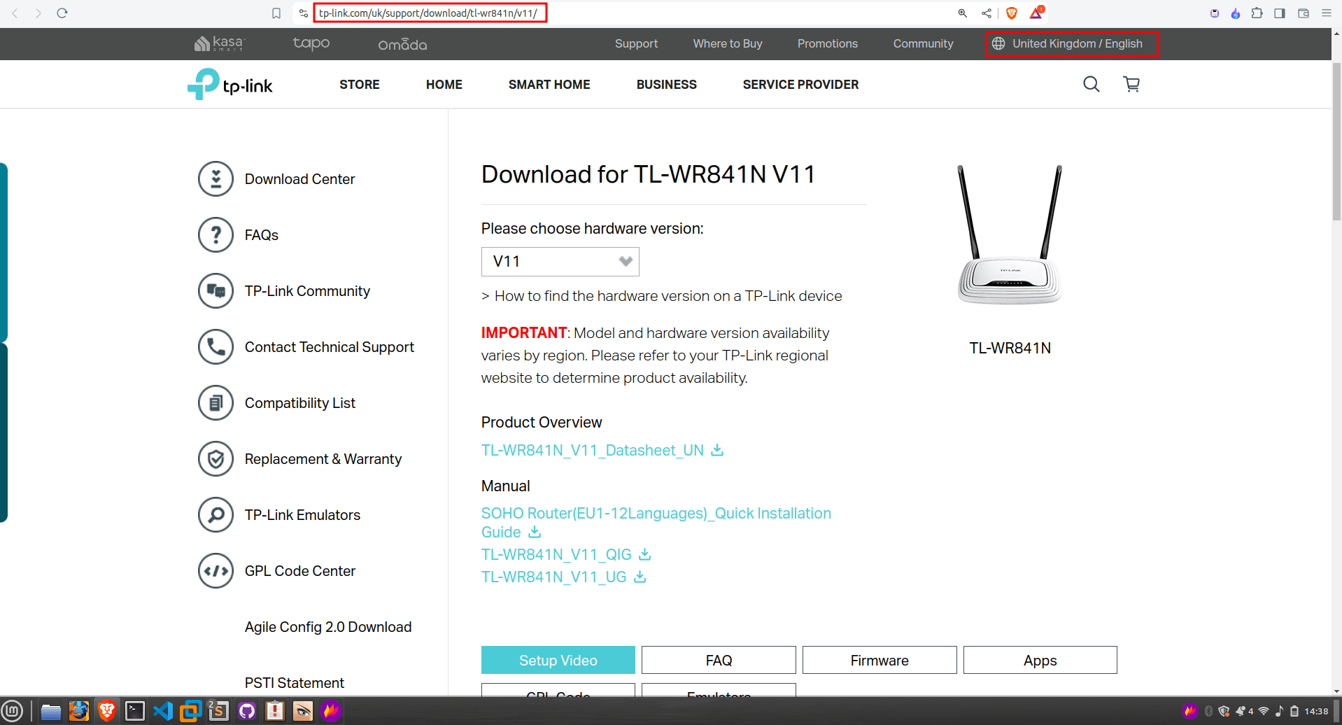
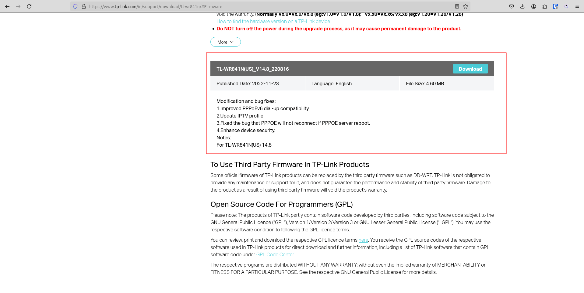
To ensure that we are testing the latest version we verified it with the website
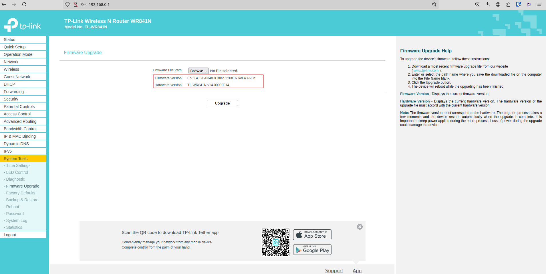
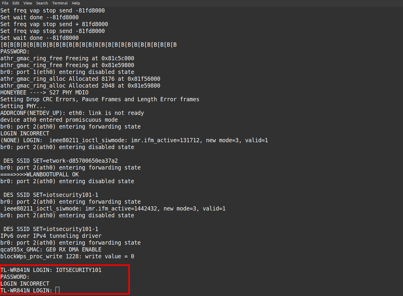
To our surprise the US version sold in Indian Continent has not protections it directly gives you a root shell, look at the image below.
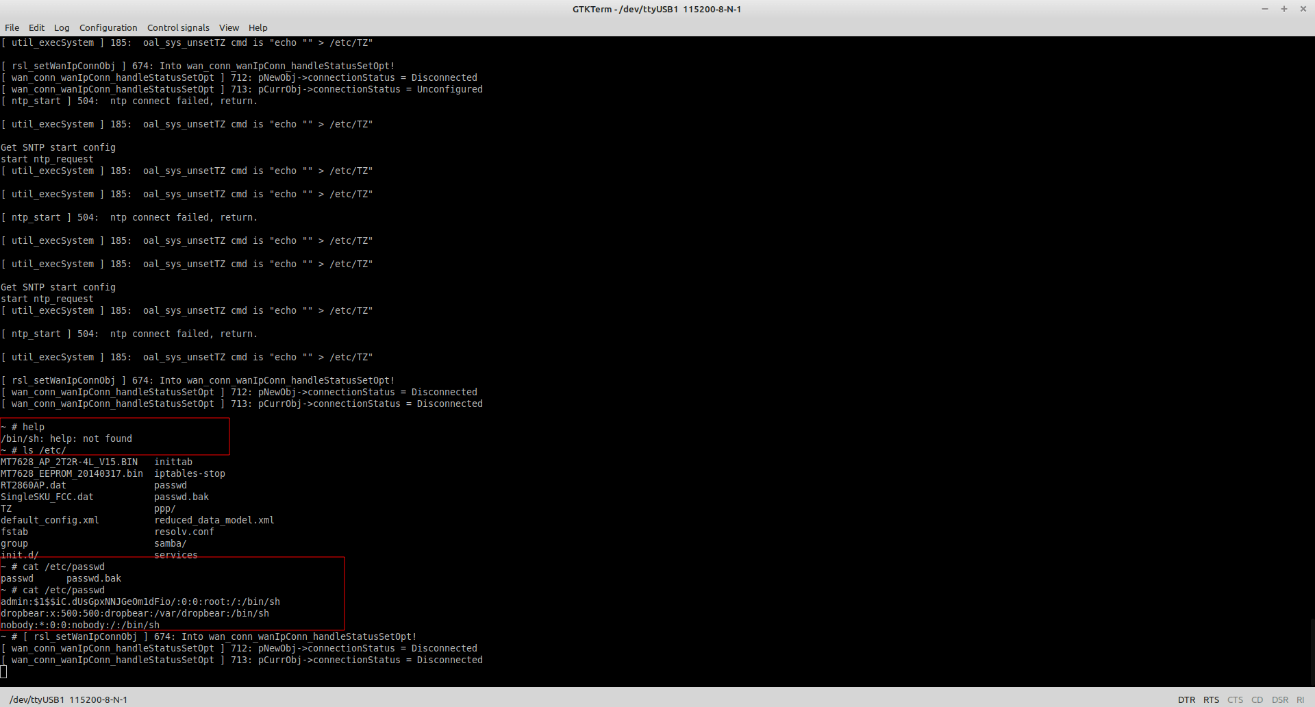
We have made use of GTKterm in here.
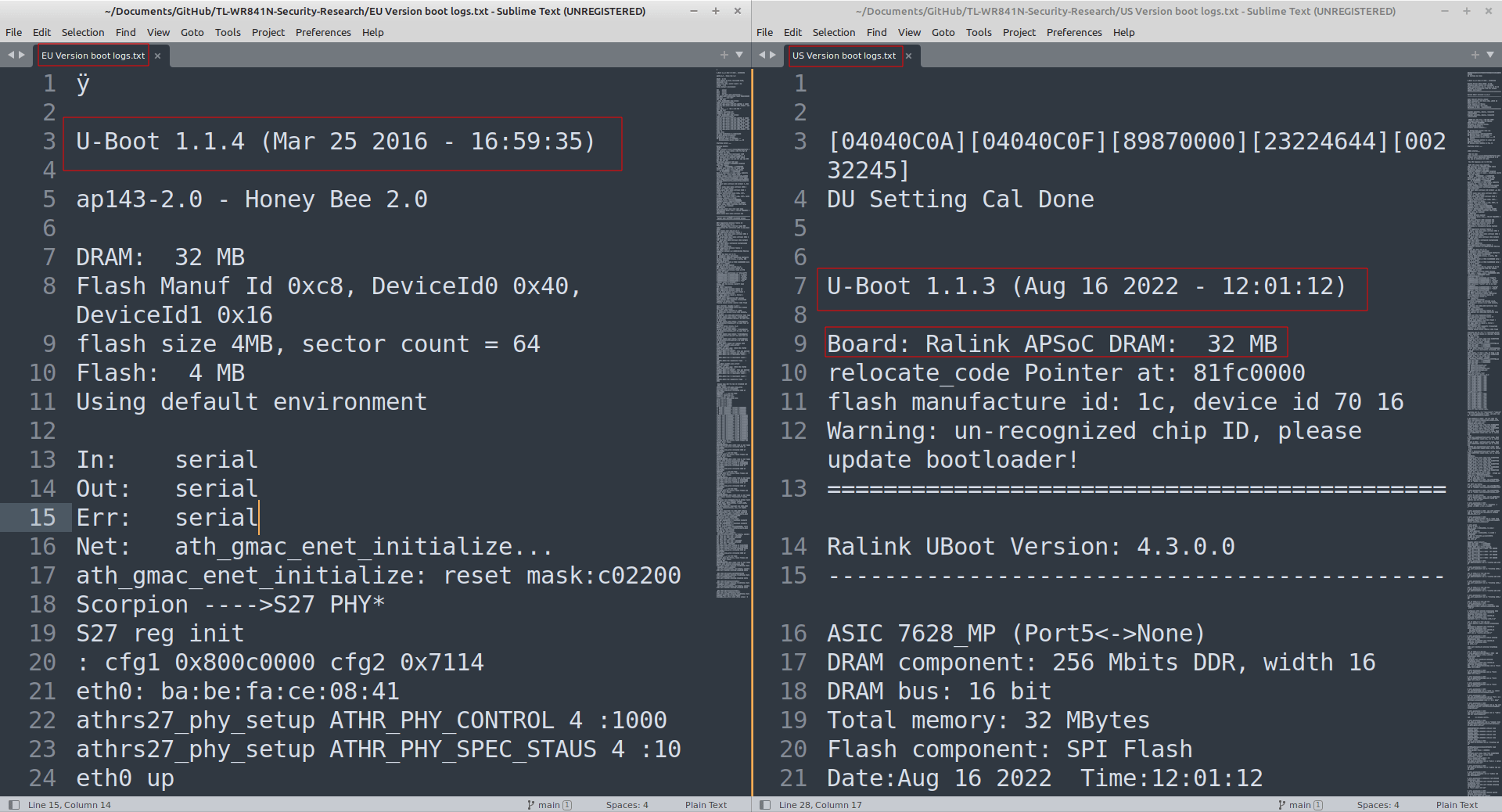
BOOT Logs
We have attached the complete boot logs for both US and EU version router
some of the differences can be noted in the serial logs as well.
6. Pull-Up and Pull-Down Resistors
Role of Resistors:
Explain the function of pull-up and pull-down resistors in the context of UART communication.
Mitigation Mechanisms:
Discuss how these resistors act as mitigations against obtaining full shell access.
- These resistors are crucial for maintaining a stable and defined logic level preventing noise and malicious signals(in our case it would be to send data on Rx line) from causing unexpected outcomes. This along with other mitigations ensures secure and reliable UART communication.
Overcoming Mitigations:
Provide insights into how you identified and overcame these resistor-based mitigations.
- Through PCB reverse engineering one can always identify mitigations in place(in our case chip resistor) and remove those to gain full functional access.
PUll up Resistor diagram
Vcc (+5V)
  |
  R_pull-up (10kΩ)
  |
Input Pin -----> Logic Circuit
  |
 GND
PUll Down Resistor text diagram
Vcc (+5V)
  |
Input Pin -----> Logic Circuit
  |
  R_pull-down (10kΩ)
  |
 GND
| Feature | Pull-Up Resistor | Pull-Down Resistor |
|---|---|---|
| Default Logic Level | High (Vcc) | Low (GND) |
| Connection to Voltage Source | Connected between input pin and Vcc | Connected between input pin and GND |
| Common Resistor Value | 1kΩ to 100kΩ (typically 10kΩ) | 1kΩ to 100kΩ (typically 10kΩ) |
| Current Flow When Active | Flows from Vcc to input pin | Flows from input pin to GND |
| Typical Use Case | Ensures input pin is high when unconnected | Ensures input pin is low when unconnected |
| Current Consumption | Lower with higher resistor values | Lower with higher resistor values |
| Susceptibility to Noise | Higher with higher resistor values | Higher with higher resistor values |
| Impact on Logic Levels | Pulls input to high logic level (Vcc) | Pulls input to low logic level (GND) |
| Application Example | Microcontroller input with push-button switch | Microcontroller input with pull-down for default low |
7. Achieving Full Shell Access
Final Steps:
Detail the final steps required to achieve full shell access after bypassing RX.
Verification:
Show how you verified that you successfully gained full shell access, including any useful outputs or screenshots.
8. Conclusion
Summary of Findings:
Summarize the key points and findings of your research.
Implications:
Discuss the broader implications of your research for router security and what it means for both consumers and security professionals.
Future Work:
Mention any potential future research directions or additional topics you plan to explore.
9. Additional Resources
References and Further Reading:
Provide links to any references, tools, or additional reading materials that could help readers understand the topic better.